|
|
Database of Waste Management Technologies |
 |
Waste to Energy 1-2: Grate incineration technology
Process Description
Grate incinerators are widely applied for the incineration of mixed municipal wastes. In Europe approximately 90 % of installations treating MSW use grates.
The grate incinerator is used for non-homegenous and low calorific waste.
The grate systems include:
- Reciprocating grates
- Roller grates
- Reversed feed grates
Grate incinerators usually have the following components:
- waste feeder
- incineration grate
- bottom ash discharger
- incineration air duct system
- incineration chamber
- auxiliary burners
The residence time of the waste onto the incineration grates does not exceed 60 minutes. The primary air supply ensures the direct combustion of the waste, while the secondary air seeks to achieve turbulent mixing of the waste in order for the combustion to be complete. In order to accomplish complete combustion of the gases it is necessary for the gases to be at a temperature above 850 °C for at least 2 seconds. The completion of the gases burn out is indicated by the levels of the carbon monoxide in the off gases. Usually auxiliary firing systems are used to keep the combustion gases at the desirable temperature levels.
The grates need to be cooled because the air is added from the bottom and high temperatures can damage the grate. Two different types of grate cooling systems exist: the air cooled grate and the water cooled grate.
The utilization of the generated heat (since combustion is an exothermic process) is most commonly made via the generation of high-pressure, superheated steam from the heat exchange between the flue gas (which absorb the majority of the heat produced) and the water/steam circuit, within a boiler.
There are two options for the utilization of this superheated steam.
- WtE 1: Produce electricity solely: The high pressure steam is driven to a turbine and generator set. The energy content of the steam is converted to kinetic energy, which is then converted to electricity via the generator. The excess heat of the low-pressure steam is cooled.
- WtE2: Produce both electricity and hot water, usually referred to as Combined Heat and Power –CHP: The high pressure steam is driven to a turbine and generator set. The energy content of the steam is converted to kinetic energy, which is then converted to electricity via the generator. The excess heat of the low-pressure steam is converted to hot water, in a condenser, and is used for district heating
Process Mass Flow Diagram

Process Photo
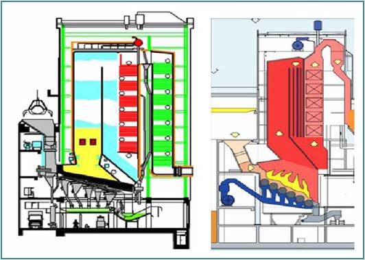
Figure 2: MSW incineration furnaces with reciprocating grate (left) and roller grate (right)
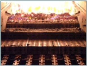
Figure 3: Moving grate
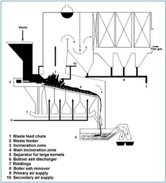
Figure 4: Grade incineration system
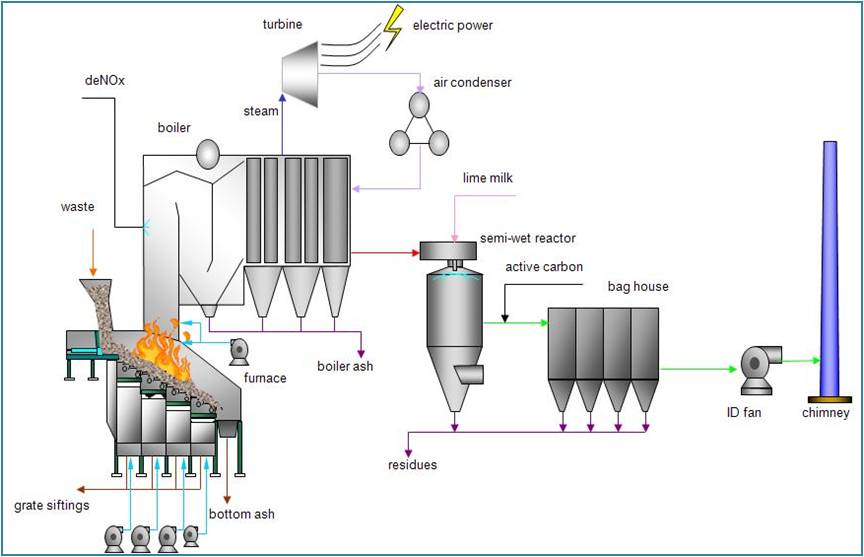
Figure 5: Example of waste to energy plant with moving grates and flue gas cleaning system
Process Operational Data
Area
A WTE facility must be accommodated in a sufficient space for the incinerator, the power unit installation and secondary facilities. According to data from various existing facilities (RIS et al. 2005) land requirements range from 0.10 to 0.25 m2 per tonne input per year, while DEFRA (2009a) reports 0.16-0.19 m2/t for grate incinerators and 0.68 m2/t for fluidized bed and Golder Associates Ltd. (2009) 0.2 -0.3 m2/t.
Energy
Energy inputs to the incineration process may include waste and imported electricity, while production and exports may include electricity transmitted in the grid and heat (as steam or hot water).
The incineration process itself requires energy for its operation e.g. pumps and fans. The demand varies greatly depending on the construction of the plant [European Commission, 2006b). In particular the process demand may be increased by:
- mechanical pre-treatment systems e.g. shredders and pumping devices or other waste preparation
- incineration air preheating
- reheat of flue-gas (e.g. for gas treatment devices or plume suppression)
- operation of waste water evaporation plant or similar
- flue-gas treatment systems with high pressure drops (e.g. filtration systems) which require higher powered forced draught fans
- decreases in the net heat value of the waste - as this can result in the need to add additional fuels in order to maintain the required minimum combustion temperatures
- sludge treatment e.g. drying.
According to data from existing WTE facilities in Europe (European Commission, 2006b), energy requirements range from 0.062 MWh to 0.257 MWh per tonne of waste feedstock for electricity and 0.021 MWh to 0.935 MWh per tonne of waste incinerated, while McDougal et al. (2002) report a specific electricity consumption of 70 kWh and 0.23 Nm3 of natural gas per tonne combusted during start-up for incinerator heating up. The energy consumption of the installation also varies according to the lower heating value of the waste. This is largely due to increased flue-gas volumes with higher net calorific waste, which require larger FGT capacity. These energy requirements are supplied by the WTE facility itself.
Although there are significant local variations, typically approx. 400 to 700 kWh of electricity can be generated with one tonne of waste in a municipal waste incineration plant. This is dependent upon the size of the plant, steam parameters and degrees of steam utilization and mainly on the lower heating value (LHV) of the waste. The lower heating value of the input waste to incinerators can be calculated from the composition using material specific LHV, which are widely available in international literature.
Since boilers attached to municipal waste incinerators must operate at lower steam temperatures to reduce corrosion, incinerators producing electricity only have a conversion efficiency of of up to 30% (McDougal et al. 2002). Energy recovery for district heating schemes, recover around 70% of energy released, whereas combined heat and power schemes, which utilize the residual heat after generation of electricity achieve an overall conversion efficiency of around 70%-90% (McDougal et al. 2002).
The amount of energy available for export usually depends upon the amount produced and the degree of self consumption by the installation - which can itself vary significantly. The FGT system consumption is often significant and varies with the type of system applied (and emission levels required). In some cases, the energy required to run the installation is imported from external supply, with all of that generated by the installation being exported – the local balance usually reflects local pricing for the electricity generated compared to general grid prices (European Commission, 2006b).
According to data from existing WTE facilities in Europe (European Commission, 2006b), electricity production ranges from 0.415 MWh to 0.546 MWh per tonne of waste incinerated, while electricity exported in the grid ranges from 0.279 MWh to 0.458 MWh per tonne of waste.
Regarding heat recovery IPPC BREF (European Commission, 2006b) reports heat production ranging from 1.376 MWh to 2.511 MWh per tonne of waste incinerated, while heat exported in the grid ranges from 0.952 MWh to 1.786 MWh per tonne. In the case of combined electricity/heat generation, approx. 1250 kWh of additional heat per tonne of waste can be used at full load (European Commission, 2006b).
Water
Water is used in waste incineration for various purposes (flue gas treatment, steam production etc), but the main consumption of water in waste incineration plants is for flue-gas cleaning. Dry systems consume the least water and wet systems generally the most. Semi-wet systems fall in between. Typical effluent rates at a MSWI are around 250kg/t of waste treated (wet scrubbing, other FGT technologies provide different figures). It is possible for wet systems to reduce consumption greatly by re-circulating treated effluent as a feed for scrubbing water. This can only be performed to a certain degree as salt can build up in the re-circulated water. The use of cooled condensing scrubbers provides a further means by which water can be removed from the flue-gas stream, which then, after treatment, can be re-circulated to the scrubbers. Salt build up remains an issue. Processes without energy recovery boilers may have very much higher water consumption. This is because the required flue-gas cooling is carried out using water injection. Consumption rates of up to 3.5 tonnes water/tonne waste are seen in such cases. Installations with a rapid quench system may use up to 20 tonnes of water per tonne of waste incinerated. The water consumption for FGT in is about 1 - 6 m3 per tonne of waste; and for sewage sludge is about 15.5 m3 per tonne of waste (European Commission, 2006b).
Process Environmental Indices
Air Emissions
The most significant pollutants emitted from mass burning of MSW are acid gases (sulphur dioxide, nitrogen oxides), carbon dioxide, particulate matter, dioxins/dibenzofurans (PCDD/PCDFs), volatile organic compounds (non-methane VOCs and methane) and heavy metals (McDougal et al. 2002, European Environmental Agency, 2009). The air emissions of WTE facilities depends on the composition of input waste, the type of incinerator, the combustion conditions and the type of flue-gas cleaning system.
The proposed emission factors of European Environmental Agency (2009), based upon data of existing WTE facilities in Europe, for mass MSW and RDF burning are summarized in the following table.
| Compound | Emission factor | Abatement type |
|---|---|---|
| SO2 | 1.7 kg/tonne | Baseline emission factor (no acid gas abatement) for mass MSW burning |
| SO2 | 2.0 kg/tonne | Baseline emission factor (no acid gas abatement) for RDF burning in fluidised bed incinerators |
| SO2 | 0.4 kg/tonne | Acid gas abatement |
| NOx | 1.8 kg/tonne | Baseline emission factor (no NOx abatement) |
| NMVOC | 0.02 kg/tonne | Baseline emission factor (uncontrolled) |
| CO | 0.7 kg/tonne | Baseline emission factor for mass MSW burning |
| CO | 1.0 kg/tonne | Baseline emission factor for RDF burning in fluidised bed incinerators |
| N2O | 0.1 kg/tonne | No NOx abatement |
| NH3 | 0 kg/tonne | Assumed neglicible |
| HCI | 2.3 kg/tonne | Baseline emission factor (no acid gas abatement) |
| HCI | 0.5 kg/tonne | Acid gas abatement |
| PM | 18.3 kg/tonne | Baseline emission factor (no particle abatement) for mass MSW burning |
| 34.8 kg/tonne | Baseline emission factor (no particle abatement) for RDF burning in fluidised bed incinerators | |
| PM | 0.3 kg/tonne | Particle abatement only |
| CO | 1.0 kg/tonne | Baseline emission factor for RDF burning in fluidised bed incinerators |
| Pb | 104 g/tonne | Baseline emission factor (no particle or acid gas abatement) for mass MSW burning |
| Pb | 100 g/tonne | Baseline emission factor (no particle or acid gas abatement) for RDF burning in fluidised bed incinerators |
| Pb | 0.8 g/tonne | Particle and acid gas abatement |
| Cd | 3.4 g/tonne | Baseline emission factor No Particle and acid gas abatement |
| Cd | 0.1 g/tonne | Particle and acid gas abatement |
| Hg | 2.8 g/tonne | Baseline emission factor (no particle or acid gas abatement) |
| Hg | 1.1 g/tonne | Particle and acid gas abatement |
| PCDD/Fs | 25-1000 μg ITEQ/tonne | No PCDD/F abatement |
| PCDD/Fs | 0.5 μg ITEQ/tonne | Particle abatement plus acid gas abatement with carbon injection |
In the international literature there are also available material-specific emission factors for WTE air emissions, which take into account the regulated air emission values and the actual performance of modern WTE facilities (Harisson et al. 2000; McDougal et al. 2002).
Wastewater
Water is used in waste incineration for various purposes (flue gas treatment, steam production etc). Wet flue-gas cleaning systems give rise to waste water whereas semi-wet and dry systems generally do not. In some cases the waste water from wet systems is evaporated and in others it is treated and discharged. According to data from existing facilities (European Commission, 2006b) the specific volume of generated wastewater ranges from 0.15 m3 to 0.3 m3 per tonne of waste incinerated. McDougall et al. (2002) reports 200 to 770 litre of wastewater from wet flue gas treatment systems per tonne of waste input. Besides the waste water from the flue-gas cleaning, waste water can also arise from a number of other sources (chimney condensates after wet scrubbing, cleaning water, boiler water, contaminated rainwater etc.) and it is estimated up to 10.000 m3/year.
Residual
Solid residues from WTE facilities arise from two main sources combustion residues (bottom ash and fly ash) and solid residues from the fuel gas cleaning system.
Mass burn of typical municipal solid wastes results in 220-390 kg of bottom ash per tonne of waste (McDougal et al. 2002, European Commission 2006b). The amount of bottom ash depends on the ash content of waste input and it can be estimated from waste composition and material specific ash content data, which are available in international literature (Harisson et al. 2000).
Dry gas cleaning systems produce approximately 45-52 kg of dust and residues per tonne of waste. The semi-dry or semi-wet systems producing 40 kg of dust, while wet scrubbing systems results in 20-30 kg of dust and 2.5-12 kg of sludge residue per tonne of waste (McDougal et al. 2002). IPPC BREF (European Commission, 2006b) reports higher amounts of residue produced (32-80 kg/t for dry systems, 40-65 kg/t for semi-dry systems and 30-50 kg/t for wet systems.)
MSW contains inorganic pollutants, of which heavy metals form an important group, which are not destroyed during incineration. The will therefore leave the incinerator either in the air emissions or bottom ash and filter dust. Due to the volume reaction involved in the incineration , considerable concentration of these materials will occur in the residues and especially in the fly ash. High concentration of pollutants means that the residuals must be handled as hazardous wastes, necessitating disposal in special hazardous waste landfills (McDougal et al. 2002).